

To view the figures and tables associated with this article, please refer to the flipbook above.
In 2002, the American Concrete Institute (ACI) adopted a design methodology for post-installed anchorage in cracked and uncracked concrete substrates. Presently, The Masonry Society (TMS) design standard does not directly address post-installed anchorage in cracked masonry elements. The applicable ICC Evaluation Service (ICC-ES) acceptance criteria approved in 2021 and 2023 prompt post-installed anchor manufacturers to test and publish strength design data in cracked masonry substrates, especially in high-seismic zones. Differences in qualification and acceptance criteria have led to distinct design methodologies for post-installed anchors in cracked masonry and cracked concrete elements.
Post-Installed Anchors in Concrete Elements Standard of Practice
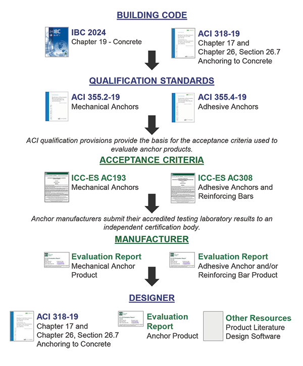
The International Building Code (IBC), Chapter 19 Concrete (IBC 2024, 1901.3) and the ACI design standard (ACI 318-19 Building Code Requirements for Structural Concrete) both directly recognize mechanical (expansion, undercut, and screw types) and adhesive post-installed anchor systems for use in concrete substrates. ACI 318-19 stipulates that mechanical and adhesive anchors meet qualification standards ACI 355.2 Qualification of Post-Installed Mechanical Anchors in Concrete and ACI 355.4 Qualification of Post-Installed Adhesive Anchors in Concrete. Independent certification bodies assess anchor testing data per acceptance criteria—AC 193 for mechanical anchors and AC 308 for adhesive anchors. Manufacturers of compliant anchors are issued a product evaluation report by the certification body indicating compliance with the building code (Fig. 1).

Cracked Concrete Post-Installed Anchor Design
Within ACI 318-19 Chapter 17 Anchoring to Concrete, 17.5 – Design Strength, Section 17.5.1.2 includes two statements. The first calls for theoretical equation-based results be confirmed via testing with “Nominal strength for an anchor or anchor groups shall be based on design models that result in predictions of strength in substantial agreement with results of comprehensive tests.” It introduces the cracked concrete requirement with “For nominal strengths related to concrete strength … influence of cracking shall be taken into account.”
The direct ACI 318-19, Chapter 17 calculation-driven influence on cracked concrete anchor capacity first appears in the basic concrete breakout strength of a single anchor in tension equation (17.6.2.2.1). The coefficient for basic concrete breakout strength in tension (kc) is applied to account for cracked concrete. For cast-in anchors (kc) is 24 while (kc) is 17 for post-installed anchors. The corresponding Commentary section indicates (kc) is derived from a large database of test results in uncracked concrete at the 5 percent fractile. The remainder of Chapter 17 includes additional cracked concrete calculation driven provisions throughout.
ACI 318-19 Section 17.10.3 requires post-installed anchors in structures assigned to Seismic Design Category (SDC) C, D, E, or F be qualified using specific ACI 355.2 and ACI 355.4 Simulated Seismic (cyclic) testing requirements. Section 17.10.5.4 and corresponding commentary state “assuming the concrete is cracked unless it can be demonstrated that the concrete remains uncracked.”
The design professional is responsible for determining whether cracked concrete requirements apply. In lieu of evaluating the potential for cracking at individual anchor locations, the design professional may conservatively design for cracked concrete conditions. For structures assigned to SDC A or B and where cracking is determined to not occur at service load levels, post-installed anchor design may use the uncracked concrete provisions.
Post-Installed Anchors in Masonry Elements—Standard of Practice
For anchoring into masonry construction, both the building code masonry chapter (IBC 2024—Chapter 21, Sections 2107 and 2108) and referenced masonry design standard (TMS 402-22 Building Code Requirements and Specification for Masonry Structures) do not contain calculation driven post-installed adhesive and mechanical anchor requirements. TMS 402-22 Chapter 8 Allowable Stress Design of Masonry, Section 8.1.4.2 and Chapter 9 Strength Design of Masonry, Section 9.1.6.2 apply to anchors “embedded in grout.” Both chapters require testing to determine the allowable loads or nominal strengths. Commentary 9.1.6 recognizes the range of post-installed anchor “configurations” and directs designers to the manufacturer’s published literature for design guidance. Commentary 9.1.6.2 notes that Section 9.1.6.3 Nominal Strengths Determined by Calculation for Headed and Bent-Bar Anchor Bolts does not address post-installed anchorage. Section 9.1.6.2 refers to ASTM C1892 Standard Test Methods for Strength of Anchors in Masonry which requires a minimum of five masonry failure mode tests (or three tests when only steel failure occurs). Final design strengths are then determined by using 65% of the average failure load and an associated phi (Φ) factor for the corresponding failure mode (Fig. 2).

Building Code Approval Path for Post-Installed Anchors in Masonry Substrates
Post-installed anchor manufacturers often provide for building code compliance through product evaluation reports, as specified in IBC 2024 Section 104.2.3.6.1 under the alternative materials provisions of Section 104.2.3. Certification bodies accredited to ISO 17065, including ICC Evaluation Service (ICC-ES) and the International Association of Plumbing and Mechanical Officials (IAPMO) Uniform Evaluation Services (UES), use acceptance criteria to verify product compliance before issuing evaluation reports. Development of new acceptance criteria begins with an application submitted to ICC-ES technical staff. ICC-ES then works with the applicants and interested parties to prepare the criteria for review by the ICC-ES Evaluation Committee. Composed of building officials, the committee uses a transparent, formal process that includes public comment and testimony at a hearing before final approval. The applicable acceptance criteria for mechanical and adhesive anchors in cracked and uncracked masonry are AC01 (24) 2nd Edition and AC58 (24) 2nd Edition, respectively. Both include anchor strength design provisions for solid or hollow clay brick units, grouted, partially grouted, and ungrouted hollow concrete masonry unit construction in cracked and uncracked conditions. As stated in the documents, the anchor strength design provisions in AC01 and AC58 are “derived substantially” from the concrete post-installed anchor provisions of ACI 318-19 Chapter 17, with masonry-specific deletions, modifications, and additions.
Cracked Masonry Post-Installed Anchor Design
TMS 402-22 does not require a cracked state or a system overstrength factor for cast-in-place or post-installed masonry anchorage. It does not distinguish between cracked and uncracked masonry states for nominal anchor strength determination testing and calculation methods. In 2019, the masonry industry considered the impact a crack has on overall post-installed anchor performance. A major revision to AC58 passed the ICC-ES Evaluation Committee adding cracked masonry testing protocols to adhesive anchors. In 2021, AC01 incorporated similar provisions for mechanical anchors (torque and displacement-controlled, undercut, and screw types) in cracked masonry elements. Compliance dates for the new acceptance criteria were April 15, 2023, for AC58 and August 15, 2026, for AC01. It should be noted that TMS 402-22 does not reference the current AC58 and AC01 criteria, or previous versions of these documents, within its provisions or commentary.
In the revised (2nd Edition) version of AC58, the calculation-driven influence of cracked masonry on post-installed adhesive anchor capacity first appears in the basic masonry breakout strength of a single anchor in tension (Nb,m) with modified equation (17.6.2.2.1) from ACI 318-19. The effectiveness factor for breakout in masonry (km=12) which includes a reduction factor (αmasonry = 0.70) applied to the concrete breakout effectiveness factor (kc = 17) for post-installed anchors.
A viable path for post-installed anchor manufacturers to certify building code compliance via a product evaluation report now includes mechanical and adhesive anchor testing per the updated AC58 and AC01 documents which incorporate cracked masonry strength design requirements.
As with the cracked concrete provisions, AC58 and AC01 call for post-installed anchors in masonry to be designed for cracked conditions when the structure is assigned to SDC C, D, E, or F, or when structural analysis indicates cracking may occur under service load conditions, including the effects of wind and seismic demands at the anchor location. The design professional is responsible for determining whether either of these conditions apply to the project or specific anchorage application. In lieu of performing an analysis to assess the potential for cracking under service load conditions, the design professional may conservatively assume a cracked masonry condition. Uncracked masonry may also be assumed when justified by analysis.
Masonry Anchor Design Paradigms: ASD & LRFD
TMS 402-22 permits both Allowable Stress Design (ASD) and Strength Design (LRFD) methodologies for the design of masonry structures and elements. The design professional has four post-installed masonry anchor design options that align with, or are alternatives to, TMS 402-22.

The first of these design options aligns with TMS 402 Chapter 8 ASD methodology and references the allowable tension and shear load values published by the anchor manufacturer based on ASTM C1892 uncracked masonry tests, with an applied factor of safety of five. The recent June 2026 adoption of ICC-ES AC585 Acceptance Criteria for Mechanical Anchors in Uncracked Masonry Construction now continues to allow manufacturers to include uncracked masonry ASD design data for their mechanical anchors that aligns with TMS 402 and IBC, as well as the legacy version of AC01. The second design option, which utilizes an alternate ASD methodology, takes the cracked or uncracked LRFD published load values provided in the anchor manufacturer’s evaluation report and divides them by a conversion factor (α) to obtain ASD load values. The conversion factor is a weighted average of the load factors for the controlling load combination. For example, in a wind load only condition the conversion factor is 1.67 [= 1/0.60].
The third design option follows TMS 402 Chapter 9 LRFD methodology and calculates design strengths using 65% of the average ASTM C1892 test failure loads and the appropriate failure mode based (Φ factor. The fourth design option, which utilizes an alternate LRFD methodology, relies on the anchor manufacturer’s published evaluation report data, compliant with the revised AC01 or AC58 criteria, to determine design strengths for both cracked and uncracked masonry.
Today, many anchor manufacturers’ evaluation reports provide strength design values based on acceptance criteria in cracked and uncracked masonry construction. The design professional looking to leverage the ASD methodology has two options: (1) convert the cracked or uncracked masonry strength design values to ASD using the conversion factor (α); or (2) locate, if available, the anchor manufacturer’s published uncracked masonry ASD data. With the recent adoption of ICC-ES AC585, and the existing TMS 402-22 provisions, some manufacturers have published evaluation reports with uncracked masonry ASD design data for their anchor products.
Post-installed Masonry Anchorage Limitations & Special Inspections
When specifying post-installed anchors in masonry, the design professional should review the applicable evaluation report for product-specific limitations and conditions of use. The evaluation report identifies restrictions related to masonry strength, installation orientation, loading conditions, inspection requirements, and required compliance with the manufacturer’s printed installation instructions. The following limitations are common for post-installed masonry anchors:
- Tested concrete masonry unit compressive strength is specific to the anchor type. Low-strength masonry ranges between a minimum of 1,500 to 2,000 psi and high-strength masonry, which is limited to fully grouted CMU, is greater than or equal to 5,000 psi.
- Tested brick masonry unit compressive strength is determined using ASTM C67 and used for normalization and test result reporting.
- Continuous special inspection for horizontally inclined installations and sustained tension loads is required for adhesive anchor systems.
- Overhead adhesive anchor installations are not permitted.
- Anchor installations are prohibited in plastic hinge zones under seismic conditions.
- Anchor installation is in accordance with the manufacturers printed installation instructions (MPII). Typically, hollow substrates require roto-hammer drill settings to use rotation only drilling mode in lieu of hammer plus rotation mode.
- Anchors are not evaluated for fatigue or shock loading applications due to the absence of an approved acceptance criteria.
- Direct structural support of fire-resistance-rated construction is prohibited.
- Anchor installations located in hollow head joints in ungrouted and partially grouted walls, as well as fully-grouted walls with closed-ended masonry unit construction, are prohibited.
- Anchor installations are permitted in the head joints of fully grouted walls constructed with open-ended masonry unit construction only.
- Screen tubes are required for adhesive anchors installed in clay brick masonry construction.
Special Inspection requirements for post-installed anchors in masonry may vary, but in general the following are common:
- Periodic or continuous special inspection shall be performed in accordance with IBC Sections 1704 and 1705, and Table 4 of TMS 602.
- Continuous special inspection is required for adhesive anchors installed in horizontally inclined orientations and designed to resist sustained tension loads.
- A Special Inspector is required for initial installations of each type and size of anchor to verify:
- Anchor types, anchor dimensions.
- Masonry type, masonry compressive strength, masonry thickness.
- Adhesive identification and expiration date.
- Roto-hammer drilling method, drill bit size, and compliance with ANSI B212.15-1994.
- Hole dimensions, hole cleaning procedures.
- Installation outside of hollow head joints.
- Anchor spacing, edge distances, end distances.
- Anchor embedment depth.
- Tightening torque.
- Adherence to the manufacturer’s printed installation instructions.
Summary
The standard of practice for post-installed anchor design in both cracked and uncracked masonry construction is different from that of concrete. The Seismic Design Category, service load levels, and other design considerations at the anchor location determine the masonry state (cracked/uncracked). Designers may follow strength design or allowable stress design methodologies. Anchor design capacities are specified in published product evaluation reports or confirmed via ASTM C1892 testing. Understanding typical masonry anchorage limitations and special inspection requirements helps ensure correct installation and optimal anchor performance. ■
Derek Gilbert, PE, is senior field engineer at Simpson Strong-Tie, bringing more than 26 years of expertise in structural engineering and AEC technology. He supports engineers, architects, and contractors by delivering practical solutions for post-installed anchors, CFS connectors, fasteners, and mass timber systems.